Generators G1 100 MVA 138 kV G2 200 MVA 150 kV Transformers
Generators
G1: 100 MVA, 13.8 kV
G2: 200 MVA, 15.0 kV
Transformers
T1: 100 MVA, 13.8 kV/230 kV, XT1=0.1 pu
T2: 200 MVA, 15.0 kV/230 kV, XT2=0.1 pu
Transmission Lines
All lines 230 kV, z = 0.08+j0.5 ohm/km
Line lengths are
Line-1=15 km,
Line-2=50 km,
Line-3=40 km,
Line-4=15 km,
Line-5=50 km
System Base Quantities
Sbase = 100 MVA (Three-phase)
Vbase = 13.8 Kv (Line-to-line) in the zone of G1
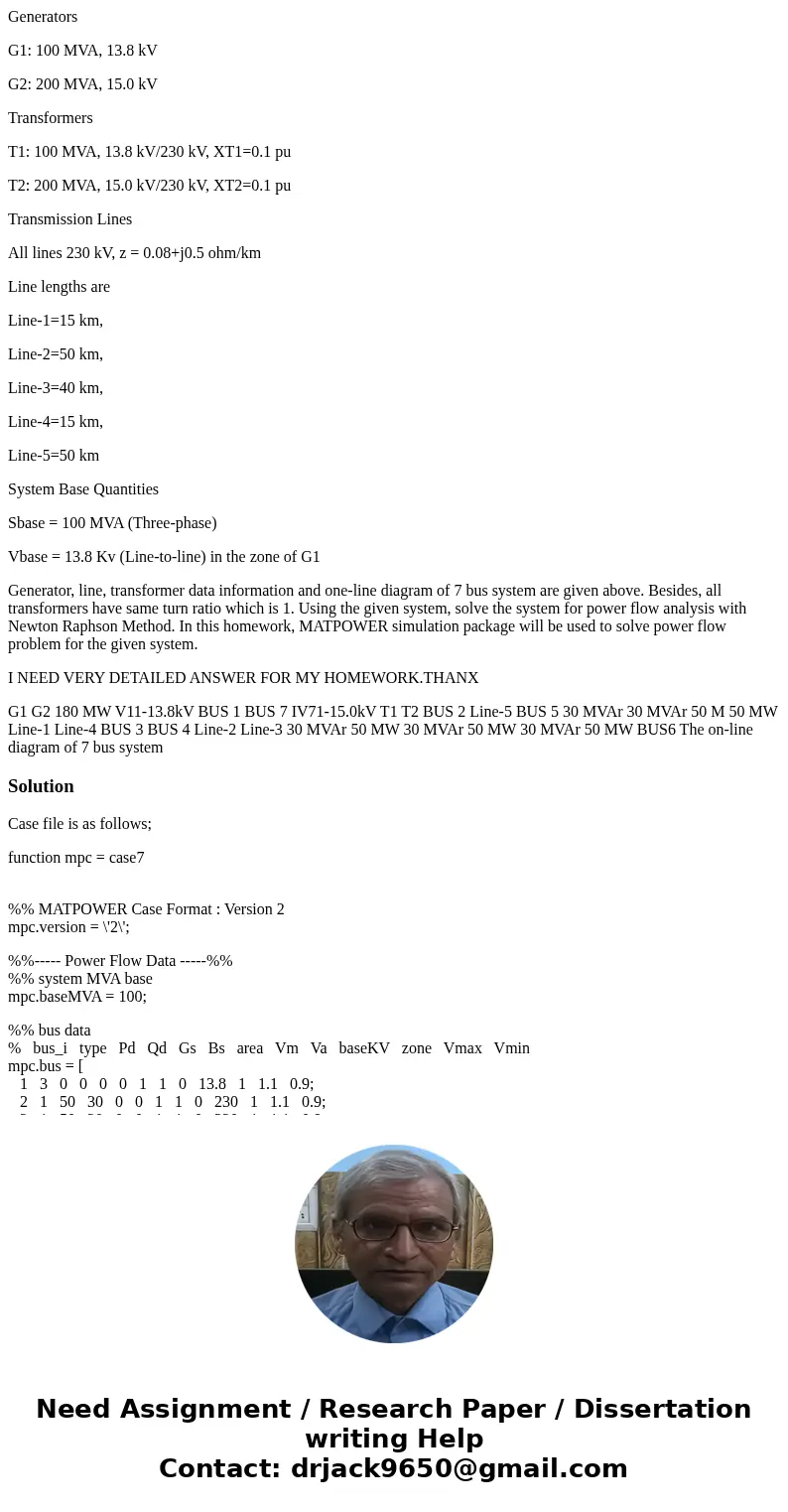
Generator, line, transformer data information and one-line diagram of 7 bus system are given above. Besides, all transformers have same turn ratio which is 1. Using the given system, solve the system for power flow analysis with Newton Raphson Method. In this homework, MATPOWER simulation package will be used to solve power flow problem for the given system.
I NEED VERY DETAILED ANSWER FOR MY HOMEWORK.THANX
G1 G2 180 MW V11-13.8kV BUS 1 BUS 7 IV71-15.0kV T1 T2 BUS 2 Line-5 BUS 5 30 MVAr 30 MVAr 50 M 50 MW Line-1 Line-4 BUS 3 BUS 4 Line-2 Line-3 30 MVAr 50 MW 30 MVAr 50 MW 30 MVAr 50 MW BUS6 The on-line diagram of 7 bus systemSolution
Case file is as follows;
function mpc = case7
%% MATPOWER Case Format : Version 2
mpc.version = \'2\';
%%----- Power Flow Data -----%%
%% system MVA base
mpc.baseMVA = 100;
%% bus data
% bus_i type Pd Qd Gs Bs area Vm Va baseKV zone Vmax Vmin
mpc.bus = [
1 3 0 0 0 0 1 1 0 13.8 1 1.1 0.9;
2 1 50 30 0 0 1 1 0 230 1 1.1 0.9;
3 1 50 30 0 0 1 1 0 230 1 1.1 0.9;
4 1 50 30 0 0 1 1 0 230 1 1.1 0.9;
5 1 50 30 0 0 1 1 0 230 1 1.1 0.9;
6 1 50 30 0 0 1 1 0 230 1 1.1 0.9;
7 2 0 0 0 0 1 1 0 15 1 1.1 0.9;
];
%% generator data
% bus Pg Qg Qmax Qmin Vg mBase status Pmax Pmin Pc1 Pc2 Qc1min Qc1max Qc2min Qc2max ramp_agc ramp_10 ramp_30 ramp_q apf
mpc.gen = [
1 0 0 300 -300 1 100 1 250 10 0 0 0 0 0 0 0 0 0 0 0;
2 180 0 300 -300 1 100 1 300 10 0 0 0 0 0 0 0 0 0 0 0;
];
%% branch data
% fbus tbus r x b rateA rateB rateC ratio angle status angmin angmax
mpc.branch = [
1 2 0 0.1 0 100/3 100/3 100/3 0 0 1 -360 360; %pu converted to actual impedance
4 5 12 7.5 0 250 250 250 0 0 1 -360 360;
5 6 40 25 0 250 250 250 0 0 1 -360 360;
3 6 40 25 0 300 300 300 0 0 1 -360 360;
5 7 0 0.05 0 200/3 200/3 200/3 0 0 1 -360 360; %pu converted to actual impedance
6 4 32 20 0 250 250 250 0 0 1 -360 360;
2 3 12 7.5 0 250 250 250 0 0 1 -360 360;
];
%%----- OPF Data -----%%
%% generator cost data
% 1 startup shutdown n x1 y1 ... xn yn
% 2 startup shutdown n c(n-1) ... c0
mpc.gencost = [
2 1500 0 3 0.11 5 150;
2 2000 0 3 0.085 1.2 600;
];
Bus type (1 = PQ, 2 = PV, 3 = ref, 4 = isolated)
RateA is MVA rating phase A line
Add folder matpower and and t inside matpower.
Check matpower with code,
test_matpower;
Result;
t_nested_struct_copy....ok
t_mpoption..............ok
t_loadcase..............ok
t_ext2int2ext...........ok
t_jacobian..............ok
t_hessian...............ok
t_margcost..............ok
t_totcost...............ok
t_modcost...............ok
t_hasPQcap..............ok
t_mplinsolve............ok (2 of 4 skipped)
t_mips..................ok
t_qps_matpower..........ok (252 of 360 skipped)
t_miqps_matpower........ok (226 of 240 skipped)
t_pf....................ok
t_cpf...................ok
t_islands...............ok
t_opf_model.............ok
t_opf_fmincon...........ok
t_opf_mips..............ok (101 of 202 skipped)
t_opf_mips_sc...........ok (101 of 202 skipped)
t_opf_dc_mips...........ok
t_opf_dc_mips_sc........ok
t_opf_dc_ot.............ok (4 of 92 skipped)
t_opf_userfcns..........ok
t_opf_softlims..........ok
t_runopf_w_res..........ok
t_dcline................ok
t_get_losses............ok
t_makePTDF..............ok
t_makeLODF..............ok
t_printpf...............ok
t_total_load............ok
t_scale_load............ok
t_psse..................ok
All tests successful (3014 passed, 686 skipped of 3700)
Elapsed time 58.64 seconds.
Now type following codes;
mpc = loadcase(case7);
runpf(case7);
result;
MATPOWER Version 5.1, 20-Mar-2015 -- AC Power Flow (Newton)
Newton\'s method power flow did not converge in 10 iterations.
>>>>> Did NOT converge (0.03 seconds) <<<<<


 Homework Sourse