What will be quantization step size in numbers and in voltag
What will be quantization step size in numbers and in voltage for this Arduino Code? Using 5V
const int led1 = 2;
const int led2 = 3;
const int led3 = 4;
void setup() {
pinMode(led1, OUTPUT);
pinMode(led2, OUTPUT);
pinMode(led3, OUTPUT);
// initialize serial communication at 9600 bits per second:
Serial.begin(9600);
}
// the loop routine runs over and over again forever:
void loop() {
// read the input on analog pin 0:
int sensorValue = analogRead(A0);
int dataConv = sensorValue*(8.0/1024);
//write analog equvivalant data on led pins
switch(dataConv)
{
case 0: {
digitalWrite(led1,LOW);
digitalWrite(led2,LOW);
digitalWrite(led3,LOW);
break;
}
case 1: {
digitalWrite(led1,HIGH);
digitalWrite(led2,LOW);
digitalWrite(led3,LOW);
break;
}
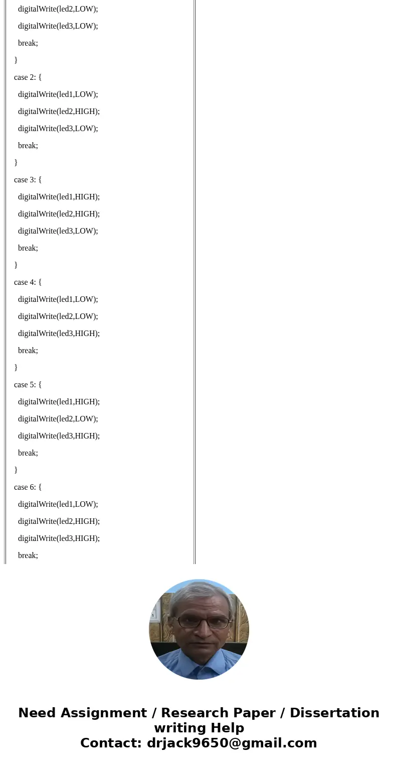
case 2: {
digitalWrite(led1,LOW);
digitalWrite(led2,HIGH);
digitalWrite(led3,LOW);
break;
}
case 3: {
digitalWrite(led1,HIGH);
digitalWrite(led2,HIGH);
digitalWrite(led3,LOW);
break;
}
case 4: {
digitalWrite(led1,LOW);
digitalWrite(led2,LOW);
digitalWrite(led3,HIGH);
break;
}
case 5: {
digitalWrite(led1,HIGH);
digitalWrite(led2,LOW);
digitalWrite(led3,HIGH);
break;
}
case 6: {
digitalWrite(led1,LOW);
digitalWrite(led2,HIGH);
digitalWrite(led3,HIGH);
break;
}
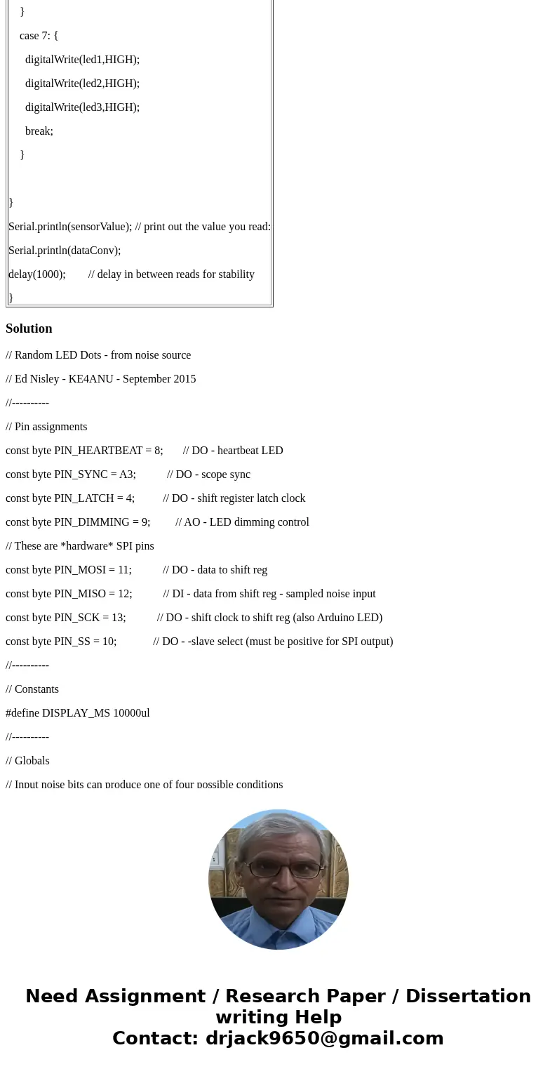
case 7: {
digitalWrite(led1,HIGH);
digitalWrite(led2,HIGH);
digitalWrite(led3,HIGH);
break;
}
}
Serial.println(sensorValue); // print out the value you read:
Serial.println(dataConv);
delay(1000); // delay in between reads for stability
}
| const int led1 = 2; const int led2 = 3; const int led3 = 4; void setup() { pinMode(led1, OUTPUT); pinMode(led2, OUTPUT); pinMode(led3, OUTPUT); // initialize serial communication at 9600 bits per second: Serial.begin(9600); } // the loop routine runs over and over again forever: void loop() { // read the input on analog pin 0: int sensorValue = analogRead(A0); int dataConv = sensorValue*(8.0/1024); //write analog equvivalant data on led pins switch(dataConv) { case 0: { digitalWrite(led1,LOW); digitalWrite(led2,LOW); digitalWrite(led3,LOW); break; } case 1: { digitalWrite(led1,HIGH); digitalWrite(led2,LOW); digitalWrite(led3,LOW); break; } case 2: { digitalWrite(led1,LOW); digitalWrite(led2,HIGH); digitalWrite(led3,LOW); break; } case 3: { digitalWrite(led1,HIGH); digitalWrite(led2,HIGH); digitalWrite(led3,LOW); break; } case 4: { digitalWrite(led1,LOW); digitalWrite(led2,LOW); digitalWrite(led3,HIGH); break; } case 5: { digitalWrite(led1,HIGH); digitalWrite(led2,LOW); digitalWrite(led3,HIGH); break; } case 6: { digitalWrite(led1,LOW); digitalWrite(led2,HIGH); digitalWrite(led3,HIGH); break; } case 7: { digitalWrite(led1,HIGH); digitalWrite(led2,HIGH); digitalWrite(led3,HIGH); break; }
} Serial.println(sensorValue); // print out the value you read: Serial.println(dataConv); delay(1000); // delay in between reads for stability } |
Solution
// Random LED Dots - from noise source
// Ed Nisley - KE4ANU - September 2015
//----------
// Pin assignments
const byte PIN_HEARTBEAT = 8; // DO - heartbeat LED
const byte PIN_SYNC = A3; // DO - scope sync
const byte PIN_LATCH = 4; // DO - shift register latch clock
const byte PIN_DIMMING = 9; // AO - LED dimming control
// These are *hardware* SPI pins
const byte PIN_MOSI = 11; // DO - data to shift reg
const byte PIN_MISO = 12; // DI - data from shift reg - sampled noise input
const byte PIN_SCK = 13; // DO - shift clock to shift reg (also Arduino LED)
const byte PIN_SS = 10; // DO - -slave select (must be positive for SPI output)
//----------
// Constants
#define DISPLAY_MS 10000ul
//----------
// Globals
// Input noise bits can produce one of four possible conditions
// Use the von Neumann extractor, discarding 00 and 11 sequences
// https://en.wikipedia.org/wiki/Randomness_extractor#Von_Neumann_extractor
// Sampling interval depends on SPI data rate
// LSB arrives first, so it\'s the earliest sample
#define VNMASK_A 0x00000001
#define VNMASK_B 0x01000000
enum sample_t {VN_00,VN_01,VN_10,VN_11};
typedef struct {
byte BitCount; // number of bits accumulated so far
unsigned Bits; // random bits filled from low order upward
int Bias; // tallies 00 and 11 sequences to measure analog offset
unsigned SampleCount[4]; // number of samples in each bin
} random_t;
random_t RandomData;
// LED selects are high-active bits and low-active signals: flipped in UpdateLEDs()
// *exactly* one row select must be active in each element
typedef struct {
const byte Row;
byte ColR;
byte ColG;
byte ColB;
} leds_t;
// altering the number of rows & columns will require substantial code changes...
#define NUMROWS 8
#define NUMCOLS 8
leds_t LEDs[NUMROWS] = {
{0x80,0,0,0},
{0x40,0,0,0},
{0x20,0,0,0},
{0x10,0,0,0},
{0x08,0,0,0},
{0x04,0,0,0},
{0x02,0,0,0},
{0x01,0,0,0},
};
byte RowIndex;
#define LEDS_ON 0
#define LEDS_OFF 255
unsigned long MillisNow;
unsigned long DisplayBase;
//-- Helper routine for printf()
int s_putc(char c, FILE *t) {
Serial.write(c);
}
//-- Useful stuff
// Free RAM space monitor
// From http://playground.arduino.cc/Code/AvailableMemory
uint8_t * heapptr, * stackptr;
void check_mem() {
stackptr = (uint8_t *)malloc(4); // use stackptr temporarily
heapptr = stackptr; // save value of heap pointer
free(stackptr); // free up the memory again (sets stackptr to 0)
stackptr = (uint8_t *)(SP); // save value of stack pointer
}
void TogglePin(char bitpin) {
digitalWrite(bitpin,!digitalRead(bitpin)); // toggle the bit based on previous output
}
void PulsePin(char bitpin) {
TogglePin(bitpin);
TogglePin(bitpin);
}
//---------
//-- SPI utilities
void EnableSPI(void) {
digitalWrite(PIN_SS,HIGH); // make sure this is high!
SPCR |= 1 << SPE;
}
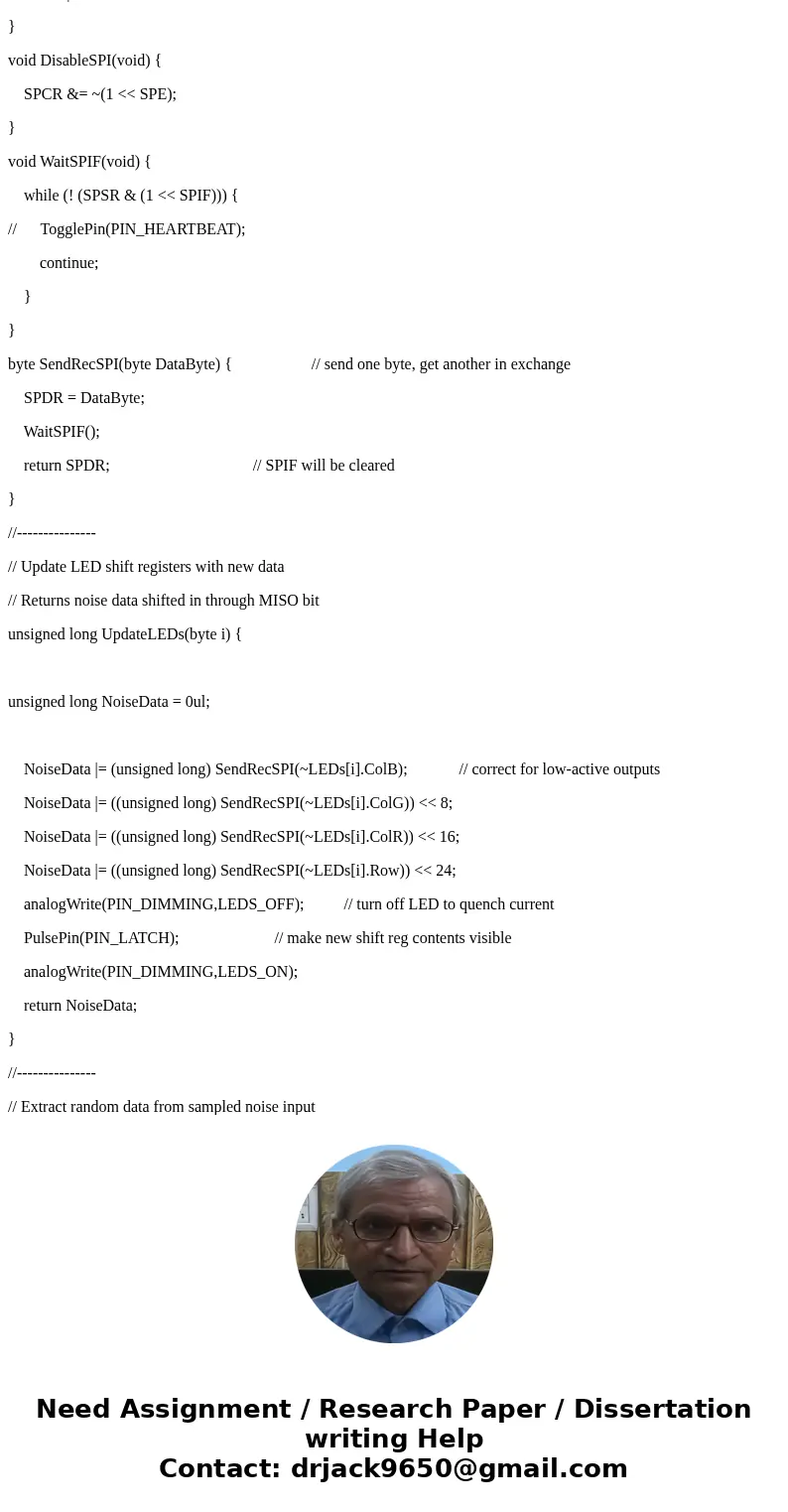
void DisableSPI(void) {
SPCR &= ~(1 << SPE);
}
void WaitSPIF(void) {
while (! (SPSR & (1 << SPIF))) {
// TogglePin(PIN_HEARTBEAT);
continue;
}
}
byte SendRecSPI(byte DataByte) { // send one byte, get another in exchange
SPDR = DataByte;
WaitSPIF();
return SPDR; // SPIF will be cleared
}
//---------------
// Update LED shift registers with new data
// Returns noise data shifted in through MISO bit
unsigned long UpdateLEDs(byte i) {
unsigned long NoiseData = 0ul;
NoiseData |= (unsigned long) SendRecSPI(~LEDs[i].ColB); // correct for low-active outputs
NoiseData |= ((unsigned long) SendRecSPI(~LEDs[i].ColG)) << 8;
NoiseData |= ((unsigned long) SendRecSPI(~LEDs[i].ColR)) << 16;
NoiseData |= ((unsigned long) SendRecSPI(~LEDs[i].Row)) << 24;
analogWrite(PIN_DIMMING,LEDS_OFF); // turn off LED to quench current
PulsePin(PIN_LATCH); // make new shift reg contents visible
analogWrite(PIN_DIMMING,LEDS_ON);
return NoiseData;
}
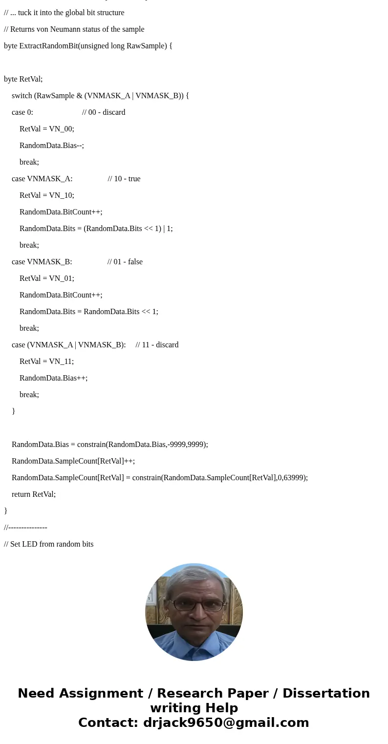
//---------------
// Extract random data from sampled noise input
// ... tuck it into the global bit structure
// Returns von Neumann status of the sample
byte ExtractRandomBit(unsigned long RawSample) {
byte RetVal;
switch (RawSample & (VNMASK_A | VNMASK_B)) {
case 0: // 00 - discard
RetVal = VN_00;
RandomData.Bias--;
break;
case VNMASK_A: // 10 - true
RetVal = VN_10;
RandomData.BitCount++;
RandomData.Bits = (RandomData.Bits << 1) | 1;
break;
case VNMASK_B: // 01 - false
RetVal = VN_01;
RandomData.BitCount++;
RandomData.Bits = RandomData.Bits << 1;
break;
case (VNMASK_A | VNMASK_B): // 11 - discard
RetVal = VN_11;
RandomData.Bias++;
break;
}
RandomData.Bias = constrain(RandomData.Bias,-9999,9999);
RandomData.SampleCount[RetVal]++;
RandomData.SampleCount[RetVal] = constrain(RandomData.SampleCount[RetVal],0,63999);
return RetVal;
}
//---------------
// Set LED from random bits
// Assumes the Value contains at least nine low-order random bits
// On average, this leaves the LED unchanged for 1/8 of the calls...
void SetLED(unsigned Value) {
byte Row = Value & 0x07;
byte Col = (Value >> 3) & 0x07;
byte Color = (Value >> 6) & 0x07;
byte BitMask = (0x80 >> Col);
// printf(\"%u %u %u %u\ \ \",Row,Col,Color,BitMask);
LEDs[Row].ColR &= ~BitMask;
LEDs[Row].ColR |= (Color & 0x04) ? BitMask : 0;
LEDs[Row].ColG &= ~BitMask;
LEDs[Row].ColG |= (Color & 0x02) ? BitMask : 0;
LEDs[Row].ColB &= ~BitMask;
LEDs[Row].ColB |= (Color & 0x01) ? BitMask : 0;
}
//------------------
// Set things up
void setup() {
pinMode(PIN_HEARTBEAT,OUTPUT);
digitalWrite(PIN_HEARTBEAT,HIGH); // show we arrived
pinMode(PIN_SYNC,OUTPUT);
digitalWrite(PIN_SYNC,LOW);
pinMode(PIN_MOSI,OUTPUT); // SPI-as-output is not strictly necessary
digitalWrite(PIN_MOSI,LOW);
pinMode(PIN_SCK,OUTPUT);
digitalWrite(PIN_SCK,LOW);
pinMode(PIN_SS,OUTPUT);
digitalWrite(PIN_SS,HIGH); // OUTPUT + HIGH is required to make SPI output work
pinMode(PIN_LATCH,OUTPUT);
digitalWrite(PIN_LATCH,LOW);
Serial.begin(57600);
fdevopen(&s_putc,0); // set up serial output for printf()
printf(\"Noisy LED Dots\ \ Ed Nisley - KE4ZNU - September 2015\ \ \");
//-- Set up SPI hardware
// LSB of SPCR set bit clock speed:
// 00 = f/4
// 01 = f/16
// 10 = f/64
// 11 = f/128
SPCR = B01110011; // Auto SPI: no int, enable, LSB first, master, + edge, leading, speed
SPSR = B00000000; // not double data rate
EnableSPI(); // turn on the SPI hardware
SendRecSPI(0); // set valid data in shift registers: select Row 0, all LEDs off
//-- Dimming pin must use fast PWM to avoid beat flicker with LED refresh rate
// Timer 1: PWM 9 PWM 10
analogWrite(PIN_DIMMING,LEDS_OFF); // disable column drive (hardware pulled it low before startup)
TCCR1A = B10000001; // Mode 5 = fast 8-bit PWM with TOP=FF
TCCR1B = B00001001; // ... WGM, 1:1 clock scale -> 64 kHz
//-- lamp test: send a white flash through all LEDs
// collects noise data to get some randomness going
printf(\"Lamp test begins: white flash each LED...\");
digitalWrite(PIN_HEARTBEAT,LOW); // turn off while panel blinks
analogWrite(PIN_DIMMING,LEDS_ON); // enable column drive
for (byte i=0; i<NUMROWS; i++) {
for (byte j=0; j<NUMCOLS; j++) {
LEDs[i].ColR = LEDs[i].ColG = LEDs[i].ColB = 0x80 >> j;
for (byte k=0; k<NUMROWS; k++) {
ExtractRandomBit(UpdateLEDs(k));
delay(25);
}
LEDs[i].ColR = LEDs[i].ColG = LEDs[i].ColB = 0;
}
}
UpdateLEDs(NUMROWS-1); // clear the last LED
printf(\" done!\ \ \");
//-- Preload LEDs with random values
// We take whatever number of random bits arrived in RandomData during lamp test
digitalWrite(PIN_HEARTBEAT,LOW);
printf(\"Preloading LED array\ \ Random bits %04x\ \ \",RandomData.Bits);
randomSeed(RandomData.Bits);
for (byte Row=0; Row<NUMROWS; Row++) {
for (byte Col=0; Col<NUMCOLS; Col++) { // Col runs backwards, but we don\'t care
LEDs[Row].ColR |= random(2) << Col;
LEDs[Row].ColG |= random(2) << Col;
LEDs[Row].ColB |= random(2) << Col;
}
UpdateLEDs(Row);
}
RandomData.BitCount = 0;
RandomData.Bits = 0;
RandomData.Bias = 0;
for (byte i=0; i<4; i++) {
RandomData.SampleCount[i] = 0;
}
check_mem();
printf(\"SP: %u HP: %u Free RAM: %u\ \ \",stackptr,heapptr,stackptr - heapptr);
printf(\"Running...\ \ \");
DisplayBase = millis();
}
//------------------
// Run the test loop
void loop() {
byte ThisBit;
MillisNow = millis();
if (RowIndex >= NUMROWS) { // set up LED row index for this pass
RowIndex = 0;
PulsePin(PIN_SYNC);
}
if ((MillisNow - DisplayBase) >= DISPLAY_MS) {
analogWrite(PIN_DIMMING,LEDS_OFF); // turn off LED to prevent bright glitch
printf(\"Bias: %5d of %5u - %5u %5u %5u %5u\ \ \",
RandomData.Bias,
RandomData.SampleCount[VN_00] + RandomData.SampleCount[VN_11],
RandomData.SampleCount[0],
RandomData.SampleCount[1],
RandomData.SampleCount[2],
RandomData.SampleCount[3]
);
RandomData.Bias = 0;
for (byte i=0; i<4; i++) {
RandomData.SampleCount[i] = 0;
}
// check_mem();
// printf(\"SP: %u HP: %u Free RAM: %u\ \ \",stackptr,heapptr,stackptr - heapptr);
DisplayBase = MillisNow;
}
// Update one LED row per pass, get at most one random bit
ThisBit = ExtractRandomBit(UpdateLEDs(RowIndex++));
// Update the heartbeat LED to show bit validity
switch (ThisBit) {
case VN_00:
case VN_11:
digitalWrite(PIN_HEARTBEAT,HIGH);
break;
case VN_01:
case VN_10:
digitalWrite(PIN_HEARTBEAT,LOW);
break;
}
// If we have enough random data, twiddle one LED
if (RandomData.BitCount >= 9) {
// analogWrite(PIN_DIMMING,LEDS_OFF); // turn off LED array to prevent bright glitch
SetLED(RandomData.Bits);
RandomData.BitCount = 0;
RandomData.Bits = 0;
}
digitalWrite(PIN_HEARTBEAT,LOW);
}







 Homework Sourse