The figure below shows a section of circuit which has four a
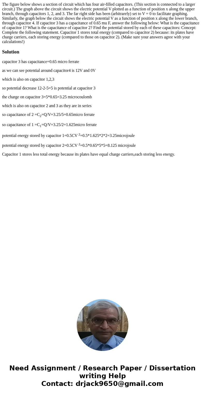
The figure below shows a section of circuit which has four air-filled capacitors. (This section is connected to a larger circuit.) The graph above the circuit shows the electric potential V plotted as a function of position x along the upper branch, through capacitors 1, 2, and 3. The far right side has been (arbitrarely) set to V = 0 to facilitate graphing. Similarly, the graph below the circuit shows the electric potential V as a function of position x along the lower branch, through capacitor 4. If capacitor 3 has a capacitance of 0.65 mu F, answer the following below: What is the capacitance of capacitor 1? What is the capacitance of capacitor 2? Find the potential stored by each of these capacitors: Concept: Complete the following statement. Capacitor 1 stores total energy (compared to capacitor 2) because: its plates have charge carriers, each storing energy (compared to those on capacitor 2). (Make sure your answers agree with your calculations!)
Solution
capacitor 3 has capacitance=0.65 micro ferrate
as we can see potential around capacitor4 is 12V and 0V
which is also on capacitor 1,2,3
so potential decrease 12-2-5=5 is potential at capacitor 3
the charge on capacitor 3=5*0.65=3.25 microcoulomb
which is also on capacitor 2 and 3 as they are in series
so capacitance of 2 =C2=Q/V=3.25/5=0.65micro ferrate
so capacitance of 1 =C1=Q/V=3.25/2=1.625micro ferrate
potential energy stored by capacitor 1=0.5CV 2=0.5*1.625*2*2=3.25microjoule
potential energy stored by capacitor 2=0.5CV 2=0.5*0.65*5*5=8.125 microjoule
Capacitor 1 stores less total energy because its plates have equal charge carriers,each storing less energy.

 Homework Sourse