Compare and contrast the serial protocols UART SPI and I2C u
Compare and contrast the serial protocols, UART, SPI and I2C using Venn diagram
Solution
UART: Stands for Universal Asynchronous Receive/Transmit. In simple terms UART relies on a baud rate agreement between receiving and transmitting controllers. The receiving MCU will expect to receive bits into its RX port at specific baud rate, for example 9600, and the transmitting MCU will transmit bits at the same baud rate, 9600. There is no master clock between the two parties, only the agreement in baud rate. Therefore the receiving MCU will know the rate that bits will flow into its RX port. Is the main protocol for serial communication in embedded and mechatronic systems, it transfers parallell data to serial on the transmitting side, and back again on the receiving side. Commonly used together with the RS-232 standard in mechatronic applications.
SPI: Stands for Serial Peripheral Interface involves a master and a slave, or multiple slaves. SPI interfacing involves 3 or more wires, consisting of a clock, serial data out, serial data in, and chip select if necessary. The master MCU basically sets the clock rate for the slaves, asks a specific one to listen up using the chip select port, and sends them commands via its serial data out port, and expects to receive the output from the slave through the serial data in port. In similarity with USART a serial transmission protocoll with the distinction of a master/slave way of communicating, in contrast to USART (UART) not able to run in asynchronous speed. In comparison to TWI/I2C it supports higher transfer speed with the cost of more I/O-pins needed, in similarity with TWI it uses a source clock line named SCKL for syncronizing the signals.
I2C: I^2 C stands for inter-integrated circuit, where every chip in the circuit has a defined address which they can be called up from. Two wires are involved, SDA and CLK. SDA is a bi-directional data flow meaning data can be accepted and sent out based on conditions set. The master sets the clock for communication, a start condition is sent by the master via SDA which tells all the slaves to listen for their address. The master then sends the address of the chip from which interfacing is desired (typically with MSB being a read or write command) and waits for an acknowledgement. After acknowledgement is received the read or write command is sent, followed by some end of transmission.
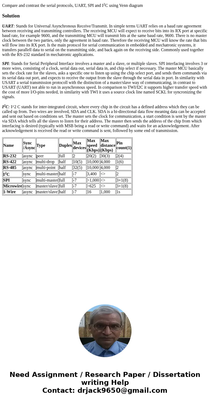
| Name | Sync /Async | Type | Duplex | Max devices | Max speed (Kbps) | Max distance (Kbps) | Pin count(1) |
| RS-232 | async | peer | full | 2 | 20(2) | 30(3) | 2(4) |
| RS-422 | async | multi-drop | half | 10(5) | 10,000 | 4,000 | 1(6) |
| RS-485 | async | multi-point | half | 32(5) | 10,000 | 4,000 | 2 |
| I2C | sync | multi-master | half | -7 | 3,400 | <> | 2 |
| SPI | sync | multi-master | full | -7 | >1,000 | <> | 3+1(8) |
| Microwire | sync | master/slave | full | -7 | >625 | <> | 3+1(8) |
| 1-Wire | async | master/slave | half | -7 | 16 | 1,000 | 1s |

 Homework Sourse