a Equation 5 of the paper is for joint members of similar ma
(a) Equation 5 of the paper is for joint members of similar materials. Determine the overall joint stiffness when the joint members are made of two different materials.
(b) Briefly describe the objective, and the effect of joint size, grip length, material and thickness combinations, hole clearance, and the bolt underhead contact radii ratio.
(c) Discuss the finite element modeling and analysis as mentioned in the paper.
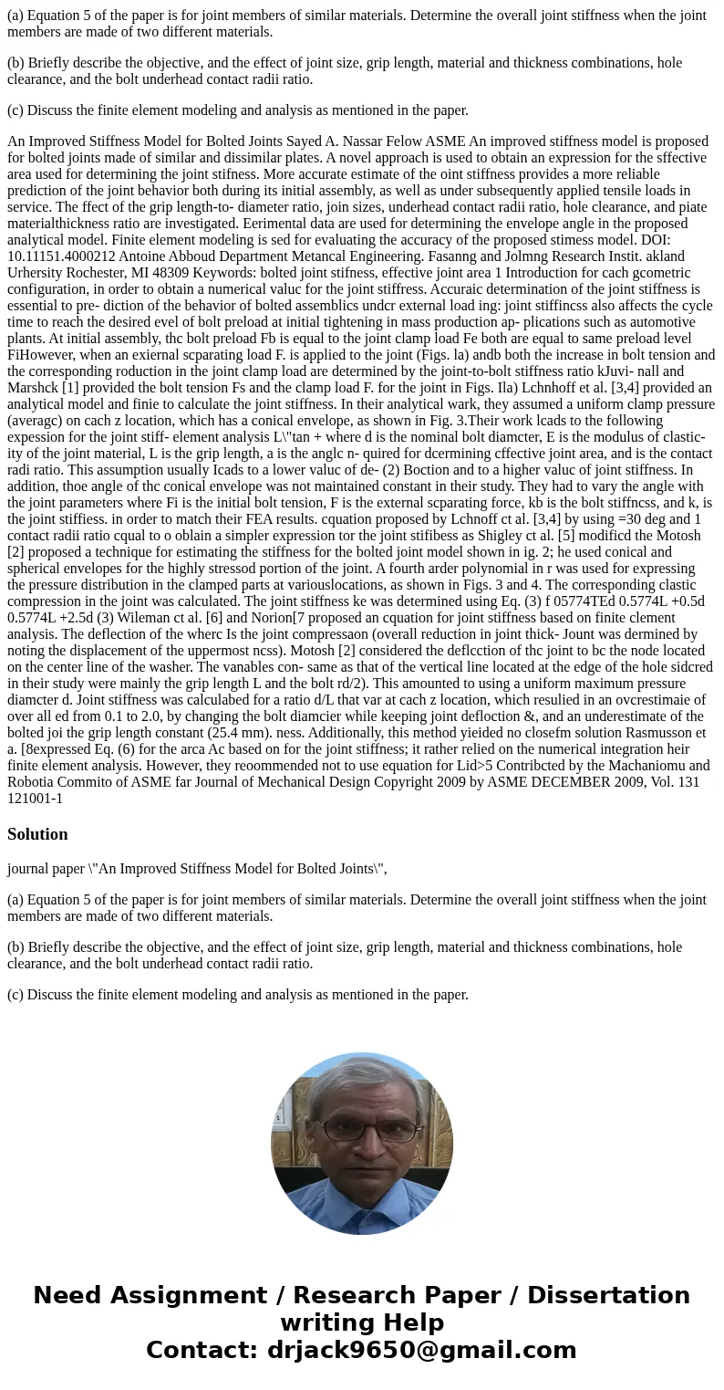
An Improved Stiffness Model for Bolted Joints Sayed A. Nassar Felow ASME An improved stiffness model is proposed for bolted joints made of similar and dissimilar plates. A novel approach is used to obtain an expression for the sffective area used for determining the joint stifness. More accurate estimate of the oint stiffness provides a more reliable prediction of the joint behavior both during its initial assembly, as well as under subsequently applied tensile loads in service. The ffect of the grip length-to- diameter ratio, join sizes, underhead contact radii ratio, hole clearance, and piate materialthickness ratio are investigated. Eerimental data are used for determining the envelope angle in the proposed analytical model. Finite element modeling is sed for evaluating the accuracy of the proposed stimess model. DOI: 10.11151.4000212 Antoine Abboud Department Metancal Engineering. Fasanng and Jolmng Research Instit. akland Urhersity Rochester, MI 48309 Keywords: bolted joint stifness, effective joint area 1 Introduction for cach gcometric configuration, in order to obtain a numerical valuc for the joint stiffress. Accuraic determination of the joint stiffness is essential to pre- diction of the behavior of bolted assemblics undcr external load ing: joint stiffincss also affects the cycle time to reach the desired evel of bolt preload at initial tightening in mass production ap- plications such as automotive plants. At initial assembly, thc bolt preload Fb is equal to the joint clamp load Fe both are equal to same preload level FiHowever, when an exiernal scparating load F. is applied to the joint (Figs. la) andb both the increase in bolt tension and the corresponding roduction in the joint clamp load are determined by the joint-to-bolt stiffness ratio kJuvi- nall and Marshck [1] provided the bolt tension Fs and the clamp load F. for the joint in Figs. Ila) Lchnhoff et al. [3,4] provided an analytical model and finie to calculate the joint stiffness. In their analytical wark, they assumed a uniform clamp pressure (averagc) on cach z location, which has a conical envelope, as shown in Fig. 3.Their work lcads to the following expession for the joint stiff- element analysis L\"tan + where d is the nominal bolt diamcter, E is the modulus of clastic- ity of the joint material, L is the grip length, a is the anglc n- quired for dcermining cffective joint area, and is the contact radi ratio. This assumption usually Icads to a lower valuc of de- (2) Boction and to a higher valuc of joint stiffness. In addition, thoe angle of thc conical envelope was not maintained constant in their study. They had to vary the angle with the joint parameters where Fi is the initial bolt tension, F is the external scparating force, kb is the bolt stiffncss, and k, is the joint stiffiess. in order to match their FEA results. cquation proposed by Lchnoff ct al. [3,4] by using =30 deg and 1 contact radii ratio cqual to o oblain a simpler expression tor the joint stifibess as Shigley ct al. [5] modificd the Motosh [2] proposed a technique for estimating the stiffness for the bolted joint model shown in ig. 2; he used conical and spherical envelopes for the highly stressod portion of the joint. A fourth arder polynomial in r was used for expressing the pressure distribution in the clamped parts at variouslocations, as shown in Figs. 3 and 4. The corresponding clastic compression in the joint was calculated. The joint stiffness ke was determined using Eq. (3) f 05774TEd 0.5774L +0.5d 0.5774L +2.5d (3) Wileman ct al. [6] and Norion[7 proposed an cquation for joint stiffness based on finite clement analysis. The deflection of the wherc Is the joint compressaon (overall reduction in joint thick- Jount was dermined by noting the displacement of the uppermost ncss). Motosh [2] considered the deflcction of thc joint to bc the node located on the center line of the washer. The vanables con- same as that of the vertical line located at the edge of the hole sidcred in their study were mainly the grip length L and the bolt rd/2). This amounted to using a uniform maximum pressure diamcter d. Joint stiffness was calculabed for a ratio d/L that var at cach z location, which resulied in an ovcrestimaie of over all ed from 0.1 to 2.0, by changing the bolt diamcier while keeping joint defloction &, and an underestimate of the bolted joi the grip length constant (25.4 mm). ness. Additionally, this method yieided no closefm solution Rasmusson et a. [8expressed Eq. (6) for the arca Ac based on for the joint stiffness; it rather relied on the numerical integration heir finite element analysis. However, they reoommended not to use equation for Lid>5 Contribcted by the Machaniomu and Robotia Commito of ASME far Journal of Mechanical Design Copyright 2009 by ASME DECEMBER 2009, Vol. 131 121001-1Solution
journal paper \"An Improved Stiffness Model for Bolted Joints\",
(a) Equation 5 of the paper is for joint members of similar materials. Determine the overall joint stiffness when the joint members are made of two different materials.
(b) Briefly describe the objective, and the effect of joint size, grip length, material and thickness combinations, hole clearance, and the bolt underhead contact radii ratio.
(c) Discuss the finite element modeling and analysis as mentioned in the paper.

 Homework Sourse