This project is to design and simulate an ALU module using V
Solution
entity fp_alu is
port(in1,in2:in std_logic_vector(31 downto 0);
clk:in std_logic;
sel:in std_logic_vector(1 downto 0);
output1:out std_logic_vector(31 downto 0));
end fp_alu;
architecture fp_alu_struct of fp_alu is
component divider is
port(
clk : in std_logic;
res : in std_logic;
GO : in std_logic;
x : in std_logic_vector(31 downto 0);
y : in std_logic_vector(31 downto 0);
z : out std_logic_vector(31 downto 0);
done : out std_logic;
overflow : out std_logic
);
end component;
component fpa_seq is
port(
n1,n2:in std_logic_vector(32 downto 0);
clk:in std_logic;
sum:out std_logic_vector(32 downto 0)
);
end component;
component fpm is
port(in1,in2:in std_logic_vector(31 downto 0);
out1:out std_logic_vector(31 downto 0)
);
end component;
signal out_fpa: std_logic_vector(32 downto 0);
signal out_fpm,out_div: std_logic_vector(31 downto 0);
signal in1_fpa,in2_fpa: std_logic_vector(32 downto 0);
begin
in1_fpa<=in1&\'0\';
in2_fpa<=in2&\'0\';
fpa1:fpa_seq port map(in1_fpa,in2_fpa,clk,out_fpa);
fpm1:fpm port map(in1,in2,out_fpm);
fpd1:divider port map(clk,\'0\',\'1\',in1,in2,out_div);
process(sel,clk)
begin
if(sel=\"01\")then
output1<=out_fpa(32 downto 1);
elsif(sel=\"10\")then
output1<=out_fpm;
elsif(sel=\"11\")then
output1<=out_div;
end if;
end process;
end fp_alu_struct;
FPA BEHAVIOUR
entity fpa_seq is
port(n1,n2:in std_logic_vector(32 downto 0);
clk:in std_logic;
sum:out std_logic_vector(32 downto 0));
end fpa_seq;
architecture Behavioral of fpa_seq is
--signal f1,f2:std_logic_vector(23 downto 0):=\"000000000000000000000000\";
signal sub_e:std_logic_vector(7 downto 0):=\"00000000\";
--signal addi:std_logic_vector(34 downto 0);
signal c_temp:std_logic:=\'0\';--_vector(34 downto 0);
signal shift_count1:integer:=0;
signal num2_temp2: std_logic_vector(32 downto 0):=\"000000000000000000000000000000000\";
signal s33:std_logic_vector(23 downto 0):=\"000000000000000000000000\";
signal s2_temp :std_logic_vector(23 downto 0):=\"000000000000000000000000\";
signal diff:std_logic_vector(7 downto 0):=\"00000000\";
----------sub calling-----------------------------------------------------------------
sub(e1,e2,d);
if(d>=\"00011100\")then
sum<=num1;
elsif(d<\"00011100\")then
shift_count:=conv_integer(d);
shift_count1<=shift_count;
num2_temp2<=num2;
--s2_temp<=s2;
--------------shifter calling---------------------------------------------------------
shift(s2,shift_count,s3);
--s33<=s3;
------------sign bit checking------
if (num1(32)/=num2(32))then
s3:=(not(s3)+\'1\');------2\'s complement
adder23(s1,s3,s4,c_out);
if(c_out=\'1\')then
shift_left(s4,d_shl,ss4);
sub(e1,d_shl,ee4);
sum<=n1(32)& ee4 & ss4;
else
if(s4(23)=\'1\')then
s4:=(not(s4)+\'1\');------2\'s complement
sum<=n1(32)& e1 & ss4;
end if;
end if;
else
s3:=s3;
-- end if;
---------------------same sign start
---------------adder 8 calling---------------
adder8(e2,d,e3);
sub_e<=e3;
num1_temp:=n1(32)& e1 & s1;
num2_temp:=n2(32)& e3 & s3;
---------------adder 23 calling---------------
adder23(s1,s3,s4,c_out);
--s2_temp<=s4;
c_temp<=c_out;
if(c_out=\'1\')then
--shift1(s4,s_1,s5);
--s2_temp<=s5;
s33<=s4;
s5:=\'1\' & s4(23 downto 1);
s2_temp<=s5;
adder8(e3,\"00000001\",e4);
e3:=e4;
--sub_e<=e4;
sum<=n1(32)& e3 & s5;
else
sum<=n1(32)& e3 & s4;
end if;
end if;
end if;
end if;----same sign end
end if;
------final result assembling----------
--sum_temp<=n1(32)& e1 & s4;
--sum<=n1(32)& e3 & s4;
end process;
end Behavioral;
FPM BEHAVIOUR
entity fpm is
port(in1,in2:in std_logic_vector(31 downto 0);
out1:out std_logic_vector(31 downto 0));
end fpm;
architecture Behavioral of fpm is
procedure adder( a,b:in std_logic_vector(7 downto 0);
sout : out STD_LOGIC_VECTOR (8 downto 0))is
variable g,p:std_logic_vector(7 downto 0);
variable c:std_logic_vector(8 downto 0);
variable sout1 :STD_LOGIC_VECTOR (7 downto 0);
begin
c(0):=\'0\';
for i in 0 to 7 loop
g(i):= a(i) and b(i);
p(i):= a(i) xor b(i);
end loop;
for i in 0 to 7 loop
c(i+1):=(g(i) or (c(i) and p(i)));
end loop;
for i in 0 to 7 loop
sout1(i):=c(i) xor a(i) xor b(i);
end loop;
sout:=c(8) & sout1;
end adder;
-------------------------------------------multiplier-------------------------------
procedure multiplier ( a,b : in STD_LOGIC_VECTOR (23 downto 0);
y : out STD_LOGIC_VECTOR (47 downto 0))is
variable temp,prod:std_logic_vector(47 downto 0);
begin
temp:=\"000000000000000000000000\"&a;
prod:=\"000000000000000000000000000000000000000000000000\";
for i in 0 to 23 loop
if b(i)=\'1\' then
prod:=prod+temp;
end if;
temp:=temp(46 downto 0)&\'0\';
end loop;
y:=prod;
end multiplier;
--------------------------end multipier-----------------------------------------------
begin
process(in1,in2)
variable sign_f,sign_in1,sign_in2: std_logic:=\'0\';
variable e1,e2: std_logic_vector(7 downto 0):=\"00000000\";
variable add_expo:std_logic_vector(8 downto 0):=\"000000000\";
variable m1,m2: std_logic_vector(23 downto 0):=\"000000000000000000000000\";
variable mantisa_round: std_logic_vector(22 downto 0):=\"00000000000000000000000\";
variable prod:std_logic_vector(47 downto 0):=\"000000000000000000000000000000000000000000000000\";
variable mul_mantisa :std_logic_vector(47 downto 0):=\"000000000000000000000000000000000000000000000000”;
variable bias:std_logic_vector(8 downto 0):=\"001111111\";
variable bias_sub:std_logic_vector(7 downto 0):=\"00000000\";
variable inc_bias:std_logic_vector(8 downto 0):=\"000000000\";
variable bias_round:std_logic_vector(8 downto 0):=\"000000000\";
begin
sign calculation
sign_in1:=in1(31);
sign_in2:=in2(31);
sign_f:=sign_in1 xor sign_in2;
FPD BEHAVIOUR
entity divider is
port(
clk : in std_logic;
res : in std_logic;
GO : in std_logic;
x : in std_logic_vector(31 downto 0);
y : in std_logic_vector(31 downto 0);
z : out std_logic_vector(31 downto 0);
done : out std_logic;
overflow : out std_logic
);
end divider;
architecture design of divider is
signal x_reg : std_logic_vector(31 downto 0);
signal y_reg : std_logic_vector(31 downto 0);
signal x_mantissa : std_logic_vector(23 downto 0);
signal y_mantissa : std_logic_vector(23 downto 0);
signal z_mantissa : std_logic_vector(23 downto 0);
signal x_exponent : std_logic_vector(7 downto 0);
signal y_exponent : std_logic_vector(7 downto 0);
signal z_exponent : std_logic_vector(7 downto 0);
signal x_sign : std_logic;
signal y_sign : std_logic;
signal z_sign : std_logic;
signal sign : std_logic;
signal SC : integer range 0 to 26;
signal exp : std_logic_vector(9 downto 0);
signal EA : std_logic_vector(24 downto 0);
signal B : std_logic_vector(23 downto 0);
signal Q : std_logic_vector(24 downto 0);
type states is (reset, idle, s0, s1, s2, s3, s4);
signal state : states;
begin
x_mantissa <= \'1\' & x_reg(22 downto 0);
x_exponent <= x_reg(30 downto 23);
x_sign <= x_reg(31);
y_mantissa <= \'1\' & y_reg(22 downto 0);
y_exponent <= y_reg(30 downto 23);
y_sign <= y_reg(31);
process(clk)
begin
if clk\'event and clk = \'1\' then
if res = \'1\' then
state <= reset;
exp <= (others => \'0\');
sign <= \'0\';
x_reg <= (others => \'0\');
y_reg <= (others => \'0\');
z_sign <= \'0\';
z_mantissa <= (others => \'0\');
z_exponent <= (others => \'0\');
EA <= (others => \'0\');
Q <= (others => \'0\');
B <= (others => \'0\');
overflow <= \'0\';
done <= \'0\';
else
case state is
when reset => state <= idle;
when idle =>
if GO = \'1\' then
state <= s0;
x_reg <= x;
y_reg <= y;
end if;
when s0 => state <= s1;
overflow <= \'0\';
SC <= 25;
done <= \'0\';
sign <= x_sign xor y_sign;
EA <= \'0\' & x_mantissa;
B <= y_mantissa;
Q <= (others => \'0\');
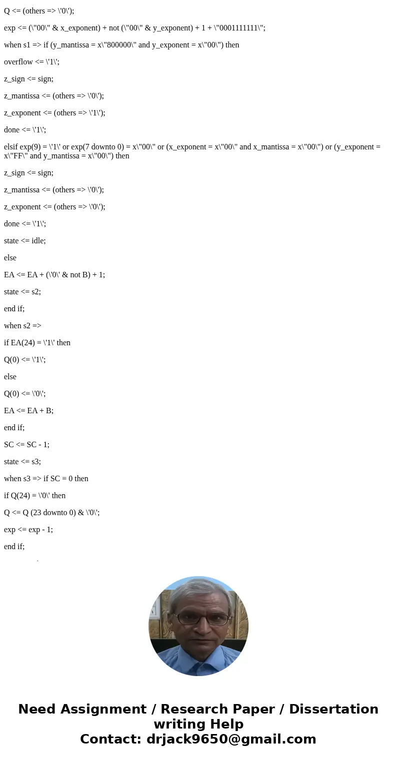
exp <= (\"00\" & x_exponent) + not (\"00\" & y_exponent) + 1 + \"0001111111\";
when s1 => if (y_mantissa = x\"800000\" and y_exponent = x\"00\") then
overflow <= \'1\';
z_sign <= sign;
z_mantissa <= (others => \'0\');
z_exponent <= (others => \'1\');
done <= \'1\';
elsif exp(9) = \'1\' or exp(7 downto 0) = x\"00\" or (x_exponent = x\"00\" and x_mantissa = x\"00\") or (y_exponent = x\"FF\" and y_mantissa = x\"00\") then
z_sign <= sign;
z_mantissa <= (others => \'0\');
z_exponent <= (others => \'0\');
done <= \'1\';
state <= idle;
else
EA <= EA + (\'0\' & not B) + 1;
state <= s2;
end if;
when s2 =>
if EA(24) = \'1\' then
Q(0) <= \'1\';
else
Q(0) <= \'0\';
EA <= EA + B;
end if;
SC <= SC - 1;
state <= s3;
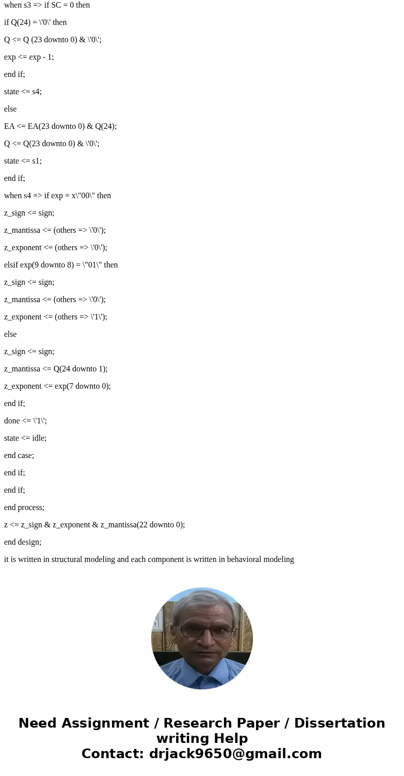
when s3 => if SC = 0 then
if Q(24) = \'0\' then
Q <= Q (23 downto 0) & \'0\';
exp <= exp - 1;
end if;
state <= s4;
else
EA <= EA(23 downto 0) & Q(24);
Q <= Q(23 downto 0) & \'0\';
state <= s1;
end if;
when s4 => if exp = x\"00\" then
z_sign <= sign;
z_mantissa <= (others => \'0\');
z_exponent <= (others => \'0\');
elsif exp(9 downto 8) = \"01\" then
z_sign <= sign;
z_mantissa <= (others => \'0\');
z_exponent <= (others => \'1\');
else
z_sign <= sign;
z_mantissa <= Q(24 downto 1);
z_exponent <= exp(7 downto 0);
end if;
done <= \'1\';
state <= idle;
end case;
end if;
end if;
end process;
z <= z_sign & z_exponent & z_mantissa(22 downto 0);
end design;
it is written in structural modeling and each component is written in behavioral modeling
 Homework Sourse